[Survey] Current Verification Methods And Their Limited Situations
Published:
by
SingularityKChen
![]() (Last updated:
)
(Last updated:
)
- Categories:
- Survey 4
- Current Verification Methods And Their Limited Situations
Current Verification Methods And Their Limited Situations
Constrained Random Verification
Introduction to CRV1
Constrained random allows you to narrow down your stimuli to those areas where coverage is lacking. CRV is an objective methodology in that you know objectively if you are done verifying your chip (as opposed to subjective measure where as soon as you stop finding bugs, you may stop simulations).
The key component missing in the traditional methodology is planning for coverage (and assertions). Without a comprehensive coverage plan, the team has no idea how their tests and testbenches are performing. They use code coverage (if) at the most. This is where CRV and coverage marry.
The first step is to create a functional coverage plan. Once the coverage plan is ready, you measure the coverage after each simulation (regression) run. This process can also be automated, and the major EDA vendors provide just such mechanisms. If the coverage is not complete, you identify the holes in your coverage results. After you constrain your stimulus, you go through the simulation cycle and repeat the coverage cycle and further identify remaining coverage holes.
Limitations of CRV in some situations
Impossible-to-think-of Corner cases1
Even the most carefully designed UVM testbench is inherently incomplete since constrained random methods can’t hit every corner case. Unfortunately, this means that even after 100% functional coverage is achieved, there can still be showstopper bugs hiding in unimagined state spaces.
And those impossible-to-think-of corner cases may be missed until very late in the project schedule, or even in the manufactured silicon, when changes are expensive and debug is highly challenging and time-consuming.
Slow simulation speed and resources consumption with large design
Simulation can be very slow (100Hz-1KHz)1 if the design is large. Also, as the testcases are randomly generated, there can be redundant testcases, which waste simulation time and computational resources.
Solutions:1
- Higher-level abstractions simulate much faster than pure RTL testbench which is modeled at signal level. Use transaction level testbench (e.g., UVM, TLM)
- Deploy well-thought-out hardware acceleration.
Difficult to reuse the IP level testcases at the SoC level
As we need to use different languages like SystemVerilog or Verilog or C or Python to create the verification environment at different levels like IPs, Sub-Systems, Chips, and SoCs, we may not be able to reuse the IP level testcases/verification environments at the SoC level. So, usually, we rewrite/modify the IP level testcases to use them at the SoC level. This is completely a manual process and it’s more time-consuming.2
Actually, this is not a really limitation of this method, but an engineering module design problem.
Solutions:
- We can define various random scenarios in UVM to model the firmware operation sequences which can eventually drive the existing lower-level IP-UVM sequences. This way we can scale-up the IP level random testcases to SoC level and do the exhaustive regression testing at the SoC level too, but still there may be many challenges of achieving coverage closure due to redundant testcases and slow simulation speed.3
- By using PSS language we can define the verification intent of any design IP/Chip/SoC and generate the verification environment in any language [testcases for simulation / emulation / FPGA prototyping] using the EDA tool.2
Static Verification (Especially formal verification)
What is static verification1
Static verification (compared to dynamic verification using simulation-based technologies) is the overarching term for a collection of techniques that use static analysis based on mathematical transformations to determine the correctness of hardware or software behavior in contrast to dynamic verification techniques such as simulation. This approach does not require a vector set and therefore does not require a testbench to be written to exercise the design. This saves time right away.
Even the most carefully designed UVM testbench is inherently incomplete since constrained random methods can’t hit every corner case. Unfortunately, this means that even after 100% functional coverage is achieved, there can still be showstopper bugs hiding in unimagined state spaces.
In contrast, SystemVerilog Assertions (properties) can test the design in all possible modes of operation and therefore can isolate bugs and undesired behavior that a designer might not have thought to test.
Additional applications of static verification technology can verify SoC connectivity correctness and completeness and help isolate differences between two disparate versions of the RTL design.
Static verification umbrella1
- Static formal verification (i.e., see that a piece of logic does not fail under any given input condition, and do this statically without the need for input simulation vectors). Note: This type of verification is also known as model checking, static functional verification, or property checking.
- Static formal plus simulation hybrid verification.
- Logic Equivalence Check (LEC). This is where you formally (i.e., without vectors) check the following for equivalency:
- RTL ⇔ RTL (critical path optimization, for example)
- RTL ⇔ gate (post-synthesis)
- Gate ⇔ gate (clock tree insertion, delay buffers for hold, etc.)
- Layout vs. schematic (LVS)
- Clock domain crossing verification.
- RTL lint.
- Structural checks.
- Low-power structural checks.
- X-state verification.
- Connectivity verification.
Pros and cons of formal verification4
Model checking is a very powerful framework for verifying specifications of finite state systems. One of the main advantages of model checking is that it is fully automated. No expert is required in order to check whether a given finite-state model conforms to a given set of system specifications. Model checking also works with partial specifications, which are often troublesome for techniques based on theorem proving. When a property specification does not hold, a model checker can provide a counterexample (an initial state and a set of transitions) that reflects an actual execution leading to an error state. This is the reason why tools based on model checking are very popular for debugging.
One aspect that can be viewed as negative is that model checkers do not provide correctness proofs. Another negative aspect is that model-checking techniques can be directly applied only to finite-state systems. An infinite-state system can by abstracted into a finite model; however, this leads to a loss of precision. Perhaps the most important issue in model checking is the state-explosion problem. It is apparent from the complexity of the CTL model checking algorithm that its practical usefulness critically depends on the size of the state space. If the number of states is too large, then the complexity of the verification procedure may render the technique unusable.
Static formal flow
- Write a property in SystemVerilog Assertion (SVA) language (or PSL—Property Specification Language or OVL for that matter).
- Supply assumptions (SVA “assume” statement) to the static formal tool.
- The static formal tool mathematically derives a model for your RTL logic under test.
- It applies all possible “stimuli” in combinational and sequential domain. It verifies that the property does not fail under any circumstance. It exercises all possible “logic cones” of a given logic block and proves that the assertion(s) are not violated.
- If the property/assertion fails, it will give the exact scenario under which the property fails. You can then simulate this scenario and debug the error at hand.
Limitations of formal verification in some situations
As upper introduces, formal verification based on mathematical transformation, and will be automatically test by the software. The former requires an accurate mathematical model with suitable abstract level, while the later requires finite states.
Missed corner cases in large modules5
With the recent trend of parallel processing units, raises the possibility of missed corner cases that simulation technologies have trouble analyzing. Although formal verification is well suited for finding corner case design bugs, current formal verification technologies are only powerful enough to verify small designs. It is still unknown how to apply formal verification consistently to larger designs or find corner cases that result from the interaction of multiple modules. Although there have been successes in using formal verification in verifying large high level designs, the verification methodology successes are time consuming and specific to a particular design.
The gap between an abstract model and a concrete model5
The other usage of formal verification is for quick verification of protocol ideas before the design process. However, in these verification efforts, it is not clear how to tie the verified protocol models with the real implementation to ensure that the design actually implement the verified model.
Bridging the gap between an abstract model and a concrete model is a problem recognized by the formal verification community even before ESL research has came onto the scene. This is because formal verification requires abstract models in order to make verification possible, and it is suggested that the correspondence between the abstract models and implementation can be verified through refinement techniques. However, all these techniques only work well for layers that are close to each other in terms of abstraction level, and there is still no practical way to link formally solvable abstract model to the RTL implementation at this time.
Hardware/Software Co-verification Using Virtual Platform with Hardware Emulation and Acceleration
Introduction to Hardware/Software Co-verification
Hardware/Software Co-verification is a methodologies to develop software such that it is ready when hardware is ready to ship.1 An SoC is ready to ship only when the complete application works, not just when hardware simulations pass regressions.
This means executing the embedded software together with the RTL. Such tests require billions of cycles of execution and usually run at the system level, where design size is the greatest.1
Virtual platform in the following can be virtual platform of the peripheral interfaces of an SoC, or it can be an ISS (Instruction Set Simulator), or it can be a virtual platform with embedded ISS:
- Virtual platform ⇔ RTL co-simulation.
- Same arguments apply for RTL ⇔ emulation co-simulation.
- Virtual platform ⇔ emulation.
- Virtual platform ⇔ hardware accelerator.
- Prototype FPGA board.
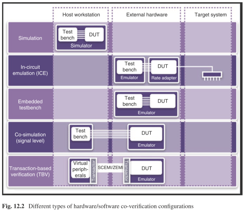
The figure shows all methodologies but the co-simulation (signal level) is not a practical methodology for software development. This is true for the “simulation” methodology. It will be too slow for hardware/software co-simulation. You would run software/hardware co-emulation, and if there is a bug, you can switch to “simulation- only” mode; run a very small snippet of code which found the bug and then debug with full visibility into your design.
Hardware/Software Co-verification Using Virtual Platform with Hardware Accelerator
Accelerator is the technology product that speeds up software simulation by orders of magnitude.
Mentor, Synopsys, and Cadence offer hardware products that allow for emulation and acceleration from the same “box.” In acceleration mode, the difference is you get excellent visibility into RTL. This allows for quick debug and turnaround time. Emulation is getting there when it comes to debug but cannot provide full visibility into RTL as acceleration does. Acceleration runs in KHz, while Emulation runs in MHz.
The emulator provided by Cadence named Palladium6, it contains a large number of simple processors, each of which simulates a small portion of the design, and then they pass the results between them.
Mentor provides Veloce which is based on custom solutions or off-the-shelf solutions. With custom solutions, there is going to be an FPGA-like structure somewhere in the device. The custom chip could also contain debug circuitry, visibility mechanisms, and a host of other capabilities
Hardware Emulation and Prototyping
Hardware emulation is the process in which a piece of hardware is made to emulate the behavior of one or more other hardware system under design. Hardware emulation is a technique that integrates a hardware design into a reconfigurable (e.g., FPGA-based) prototyping platform to allow the functional testing of a design under test including its firmware.1
Emulation is the verification method between the simulation and the FPGA prototype, which is faster than the simulation and able to provide more details than the FPGA prototype.
Limitations of emulation in some situations
Slow to compile
One of the factors that affect selection of an emulation system is the compile (synthesis) times to put RTL into the box. What good does it do for emulation to provide results in minutes while compile times take hours. Hardware emulators can accommodate any design size, but they require a long setup time and are relatively slow to compile, compared to simulation. 1
**However, in some cases, it takes weeks to run the simulation but minutes to execute it in the hardware platform. Therefore, its worthy to waiting for the compiling results.** So it's suit for the deign which is too slow to simulate tens of seconds clock cycles.
Solution:
- Compiling several versions of the design at one time and execute them.
The design is too big to fit into the target hardware7
FPGA-based design emulation is very fast, but involves structural drawbacks. The major problem occurs, if the number of gates exceeds the total or a critical gate count of the available target FPGA after synthesis. Then, the optimal clock rate of the design cannot be achieved.
Solution:
- Partition the entire design into particular hardware modules.
Difficult to debug without other verification methods
Also, the debug method based on the hardware emulation and acceleration is not as advanced as simulation. In some complex situations, you need to back to the slow simulation to debug after you find a bug.
Solution:
- Emulators like Palladium can provide some visible debugging information and trigger the signal by adding those information into the model. However, writing the model, per se, is quite tough.
Summary
Formal verification fits well in small modules with finite states, hence at the beginning of one project, we're supposed to utilize formal verification or a hybrid with simulation.
With the states of the circuits growing, a CRV based verification is needed to verify the control logic and interconnections.
Emulation might be needed in high clock frequency situations, i.e., emulating seconds or even minutes in real circuits, which is near impossible using simulation.
-
Mehta, Ashok B. "ASIC/SoC functional design verification." Publ. Springer (2018). ↩ ↩2 ↩3 ↩4 ↩5 ↩6 ↩7 ↩8 ↩9 ↩10
-
S. P. R, “PSS – Portable Test and Stimulus Standard,” Maven Silicon, Mar. 24, 2020. https://www.maven-silicon.com/blog/portable-test-and-stimulus-standard/ (accessed Jan. 11, 2021). ↩ ↩2
-
S. P. R, “IP vs SoC Verification,” Maven Silicon, Mar. 17, 2020. https://www.maven-silicon.com/blog/ip-vs-soc-verification/ (accessed Jan. 11, 2021). ↩
-
E. M. Clarke, W. Klieber, M. Nováček, and P. Zuliani, “Model Checking and the State Explosion Problem,” in Tools for Practical Software Verification, Sep. 2011, pp. 1–30, doi: 10.1007/978-3-642-35746-6_1. ↩
-
J. C. Chang, “Formal Verification Along with Design for Transactional Models,” UCB. ↩ ↩2
-
Palladium Z1 Enterprise Emulation Platform, https://www.cadence.com/en_US/home/tools/system-design-and-verification/acceleration-and-emulation/palladium-z1.html# ↩
-
R. Beckert, T. Fuchs, St. Ruelke, and W. Hardt, “A Tailored Design Partitioning Method for Hardware Emulation,” in 18th IEEE/IFIP International Workshop on Rapid System Prototyping (RSP ’07), Porto alegre, Brazil, May 2007, pp. 99–105, doi: 10.1109/RSP.2007.10. ↩