[Workshop] Using UPF for Low Power Design and Verification
- Using UPF for Low Power Design and Verification
- Low Power Design and Verification Challenges
- Introduction to UPF
- UPF Basic Concepts and Terminology
- UPF Semantics and Usage
- Hard IP Modeling with Liberty and Verilog
- Power Management Cell Commands and Power Models
- Low Power Design Methodology for IP Providers
- SoC-Level Design and Verification Challenges
- Adopting UPF
Using UPF for Low Power Design and Verification
Low Power Design and Verification Challenges
Low Power Design Challenges
- Power density is increasing every process node
- Higher performance
- Lower area
- Designs are thermally limited
- No single technique serves all purposes
- Aggressive power gating is used to minimize leakage
- Number of power domains and supplies on chip is increasing
- Early architecture decisions impacts power, so early power exploration is critical
SoC Low Power Design Challenges
- Reducing power with:
- low area overhead
- high performance
- low schedule impact
- Early power estimation and budgeting
- Silicon variation
- Correlation of models with Si data
- Lack of use case vectors
- Power aware flow
- Making all phases of design power aware
- Capturing power intent accurately
- Ensuring power intent is correctly implemented
- Verifying power intent with firmware/Software drivers
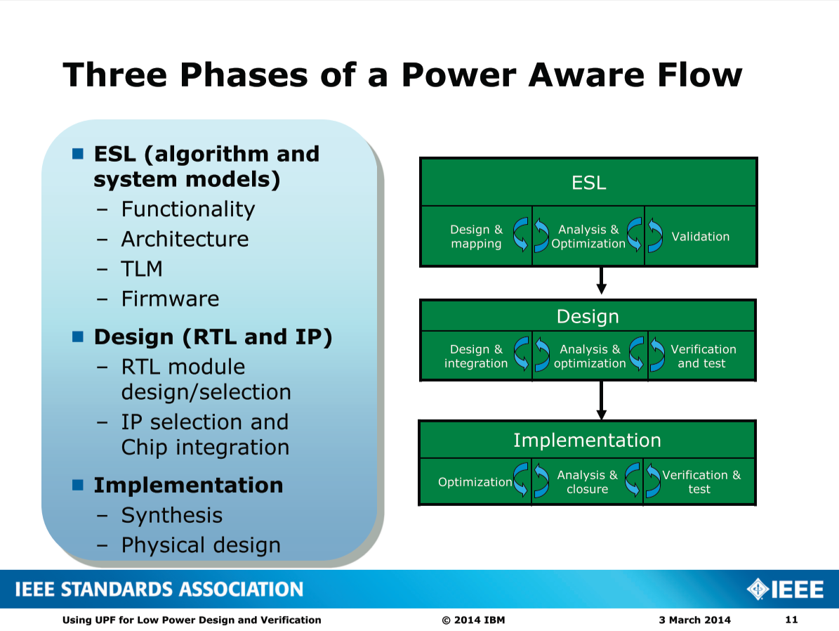
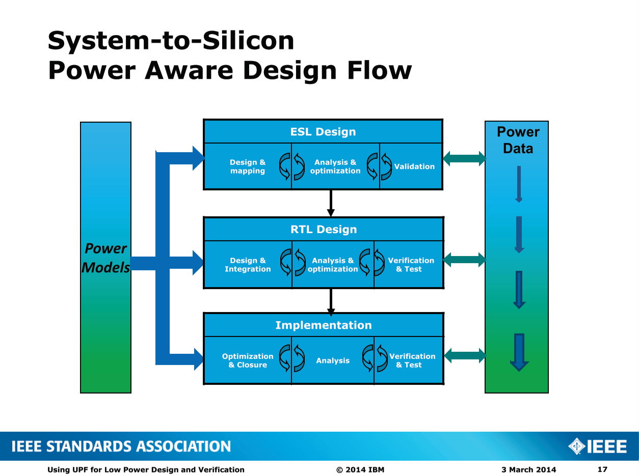
Three Phases of a Power Aware Flow
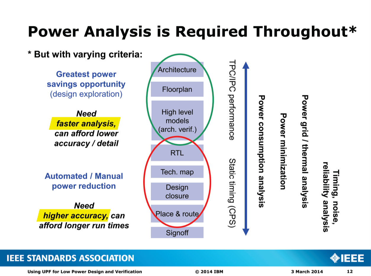
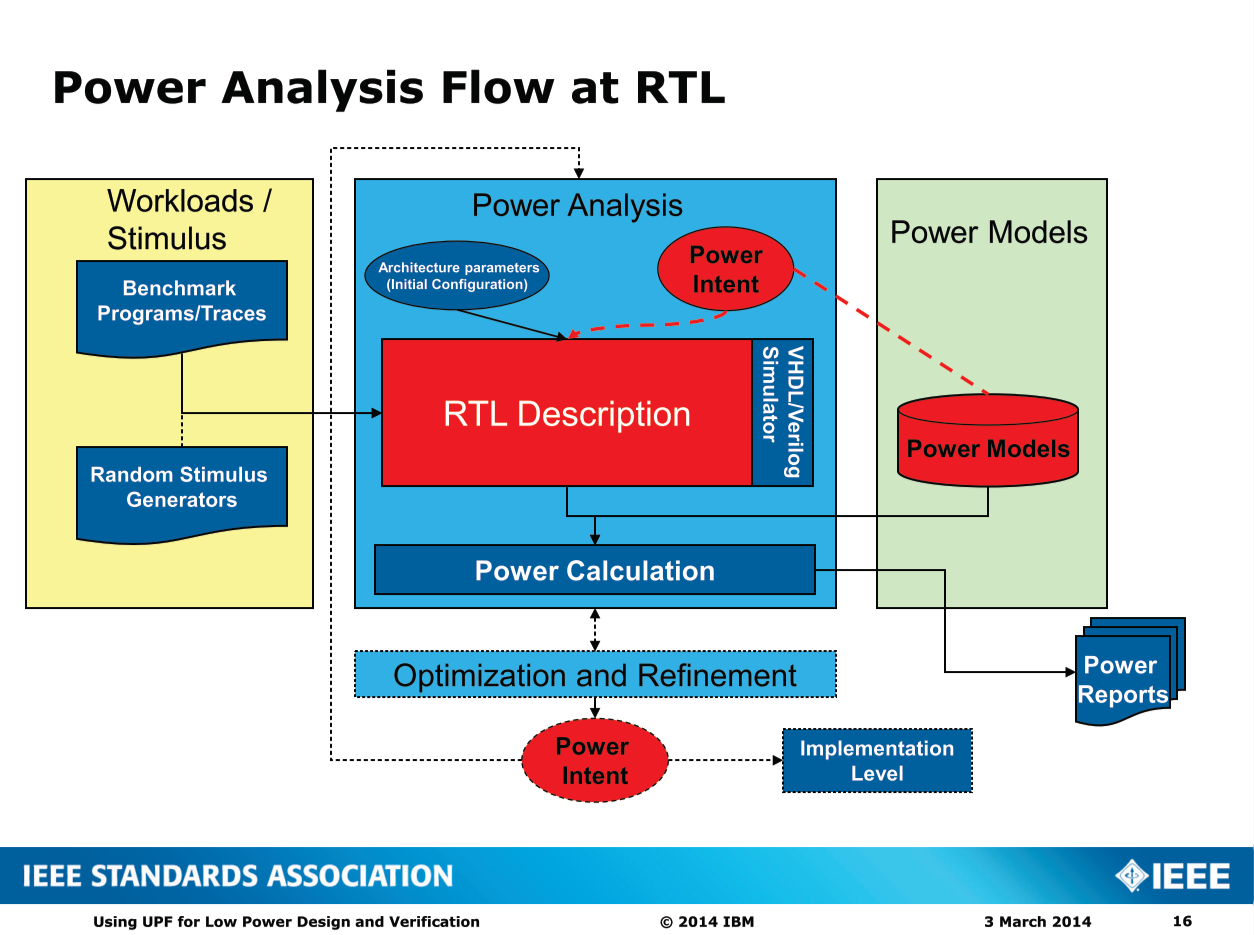
Power Analysis is Required Throughout
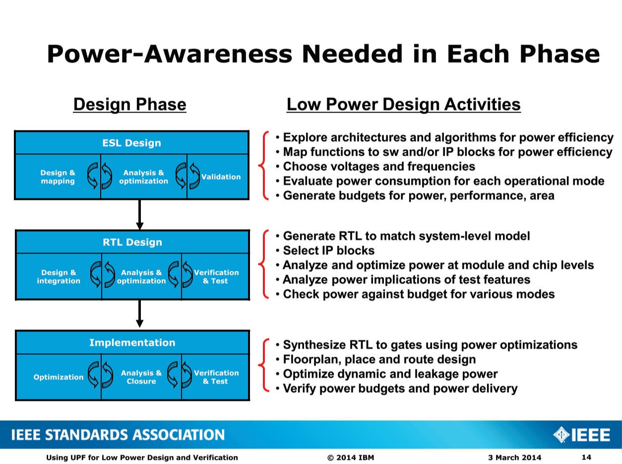
Power-Awareness Needed in Each Phase
SoC Low Power Verification Challenges
- Modeling issues
- Are all the low power features correctly represented?
- Capacity issues
- Number of domains
- Size of the chip
- Complexity issues
- Chip-level power state complexity
- Complex interactions between blocks
- Coverage issue
- Power state coverage
- System level use cases
- H/W-S/W co-verification
Where Does UPF Fit In?
- UPF models active power management
- A form of power optimization
- UPF Power Intent applies at RTL and GL (gate-level) today
- RTL for “early” verification and to drive implementation flow
- GL for verification of implementation stages
- UPF concepts can be extended to other models
- Power states and transitions in particular
- Component-based modeling paradigm can also apply
Introduction to UPF
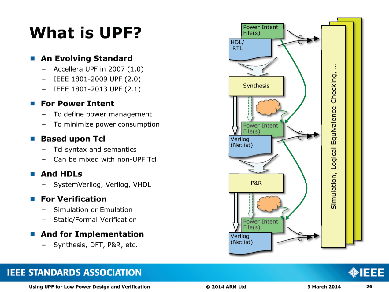
What is UPF?
Components of UPF
- Power Domain:
- Groups of elements which share a common set of power supply requirements
- Power Supply Network
- Abstract description of power distribution (ports, nets, sets & switches)
- Power State Table
- The legal combinations of states of each power domain
- Isolation Strategies
- How the interface to a power domain should be isolated when its primary power supply is removed
- Retention Strategies
- What registered state in a power domain should be retained when its primary power supply is removed
- Level Shifter Strategies
- How signals connecting power domains operating at different voltages should be shifted
- Repeater Strategies
- How domain ports should be bufffered
UPF Basic Concepts and Terminology
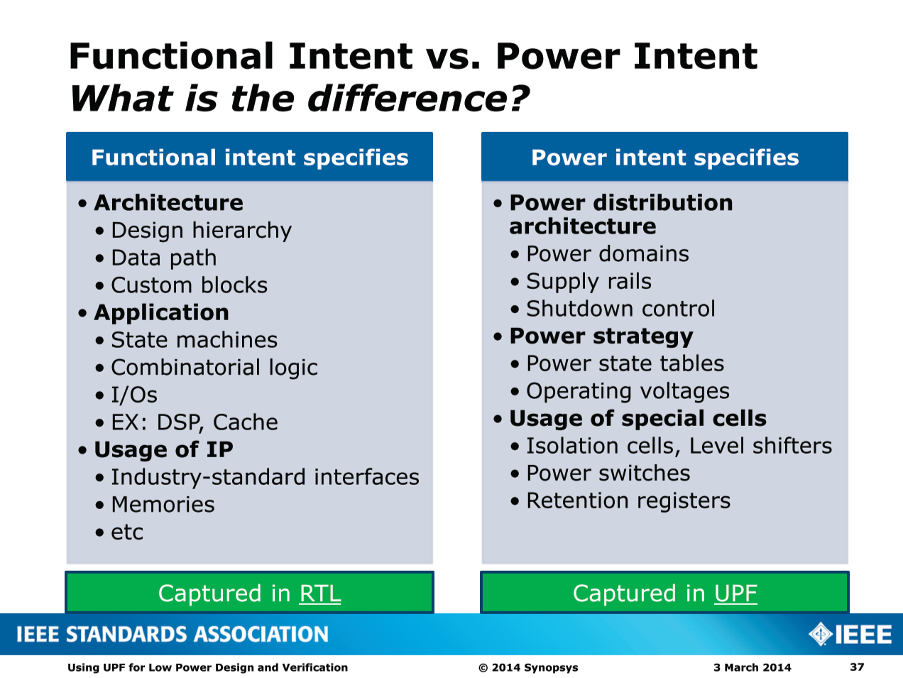
Functional Intent vs. Power Intent
How Power Intent Affects Implementation
- The power intent will have an impact on the implementation of the design.
- Domains may need separate floorplans/regions.
- Cells may need special power routing.
Power Domains
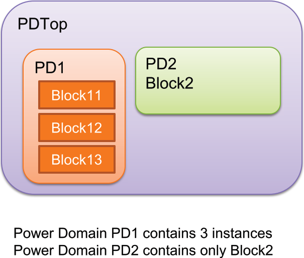
- A collection of instances that are treated as a group for power management purposes. The instances of a power domain typically, but do not always, share a primary supply set.
In UPF:
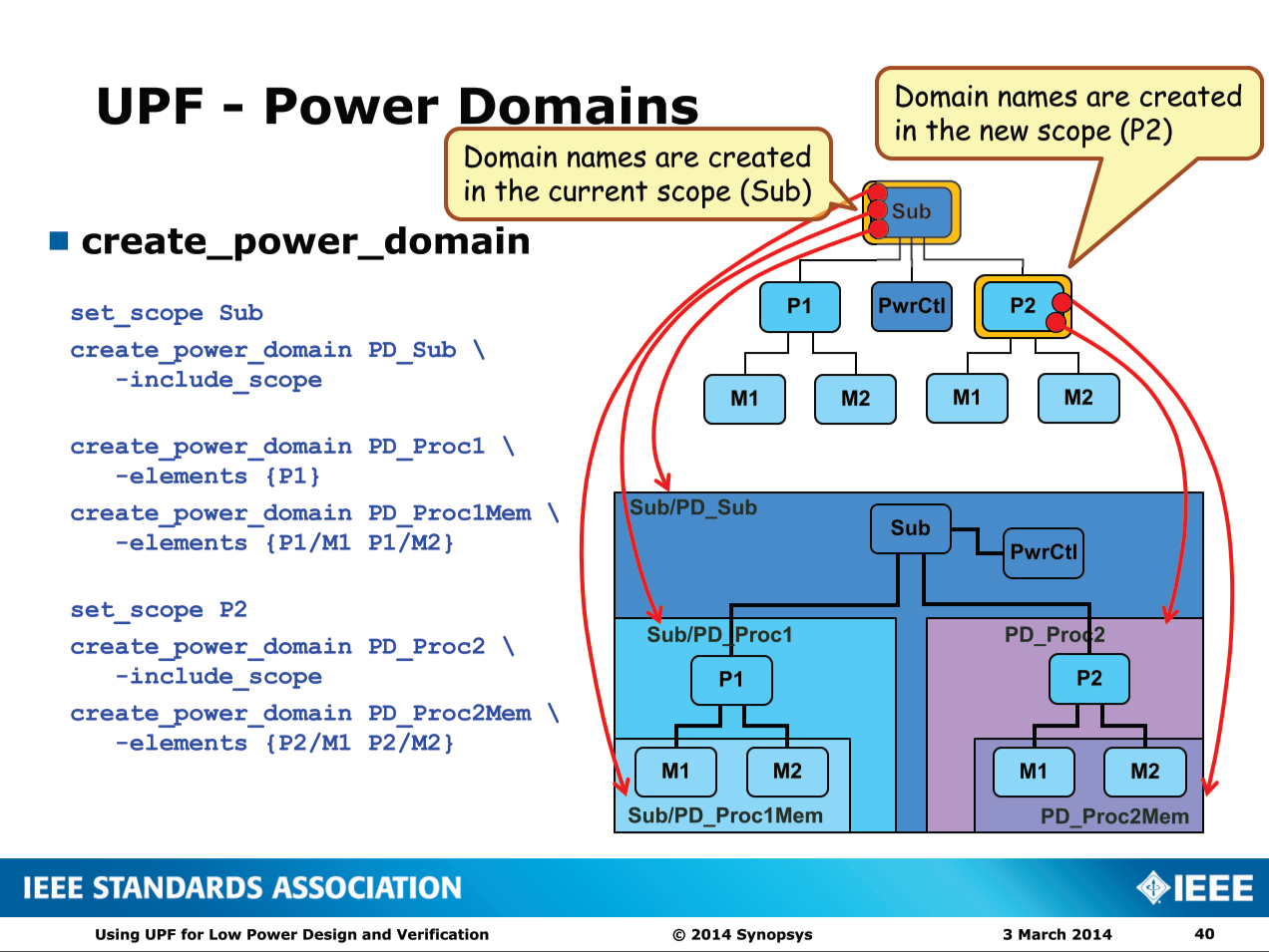
set_scope Sub
create_power_domain PD_Sub \
    -include_scope
create_power_domain PD_Proc1 \
    -elements {P1}
create_power_domain PD_Proc1Mem \
    -elements {P1/M1 P1/M2}
set_scope P2
create_power_domain PD_Proc2 \
    -include_scope
create_power_domain PD_Proc2Mem \
    -elements {P2/M1 P2/M2}
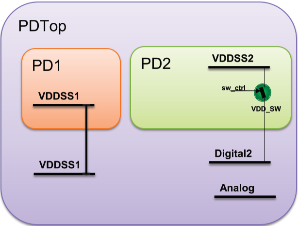
Power Supply Network
- Describes logical connectivity of the power supplies, or power rails in your design
- May include connectivity through power switches
In UPF:
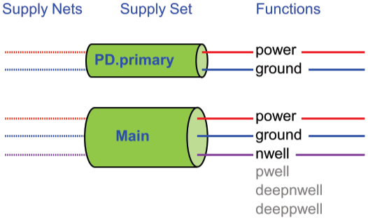
- A group of related supply nets
- Functions represent nets
- which can be defined later
- Electrically complete model
- power, ground, etc.
- Predefined supply sets
- for domains
- User-defined supply sets
- for domains (local)
- standalone (global)
- Supply set parameters
- for strategies
create_power_domain PD \
    -supply {primary} \ # (predefined)
    -supply {backup} # (user-defined)

create_supply_set Main \ # (user-defined)
    -function {power} \
    -function {ground} \
    -function {nwell}

set_isolation ISO –domain PD \
    -isolation_supply_set PD.backup
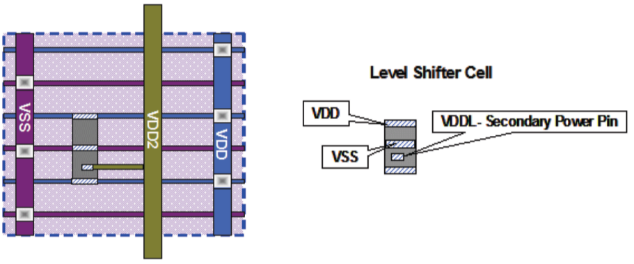
How Logical Supply Networks Relate to Real World Connections
- The functions in a supply set will translate into real supply net connections.
- Often a domain’s
primaryfunction will be implemented as the rails within a floorplan region, VDD and VSS in this example. - The other functions will be routed as secondary supplies and connect to special pins on the cell. The example here shows a levelshifter cell with a secondary pin called VDDL that connects to VDD2.
- Secondary supplies may be primary supplies of other domains. Therefore the location of special cells may result in supplies from other domains to be available at the location where the cell is inserted.
- Often a domain’s
create_supply_set top_ss\
    -function {power VDD} \
    -function {ground VSS}
associate_supply_set top_ss\
    -handle PD.primary
Power Management Techniques
Power Gating
- Power reduction technique to save leakage power by shutting off, or powering down, unnecessary logic
- Enabled by power switch, or MTCMOS, cells
- Requires consideration of
isolatingandstate retention.
Multi-voltage
- Power savings technique to operate different blocks of logic at different voltages
- Less critical blocks can be operated at a lower voltage for power savings
Bias Voltage
- Used to change the threshold voltage of a cell to improve the leakage characteristics of the cell
Dynamic Voltage and Frequency Scaling
- Power Saving Technique to change the voltage and/or clock frequency while the chip is running to save power
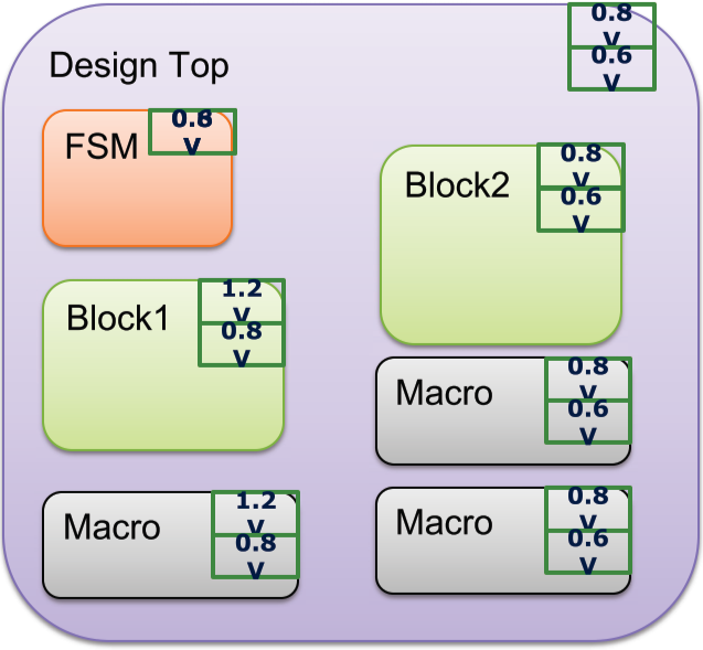
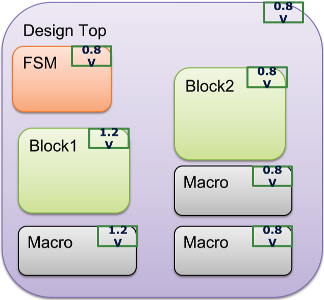
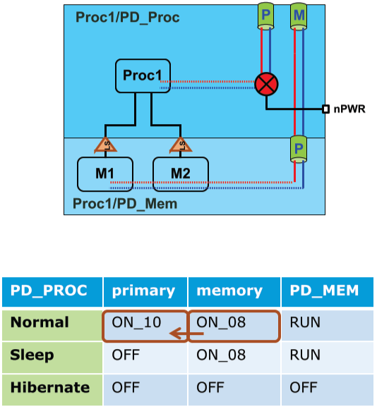
Power Management Architecture
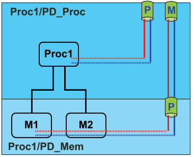
Power States and Transitions
- A design may have multiple modes of operation that affect the power supplies.
- Normal, Sleep, Hibernate
- Modelling these modes will allow tools to verify and implement the power intent. For example;
- Simulation: States can indicate that correct isolation has been specified.
- Implementation: Correct levelshifting can be inserted.
- Verification: Confirm that the design is still correct after optimization.
- UPF uses
add_power_stateto define the states of supplies.
add_power_state PD_Mem \
    -state RUN {-logic_expr {primary == ON_08}} \
    -state OFF {-logic_expr {primary == OFF}}
add_power_state PD_Proc \
    -state Normal { \
        -logic_expr {primary == ON_10 && \
                     memory == ON_08 && \
                     PD_Mem == RUN} } \
    -state Sleep { \
        -logic_expr {primary == OFF && \
                     memory == ON_08 && \
                     PD_Mem == RUN} } \
    -state Hibernate { \
        -logic_expr {primary == OFF && \
                     memory == OFF && \
                     PD_Mem == OFF} }
| PD_PROC | primary | memory | PD_MEM |
|---|---|---|---|
| Normal | ON_10 | ON_08 | RUN |
| Sleep | OFF | ON_08 | RUN |
| Hibernate | OFF | OFF | OFF |
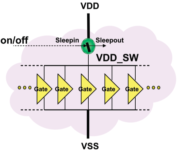
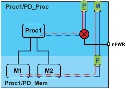
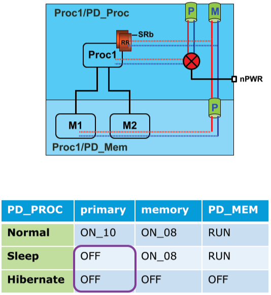
Supply switching
- Supplies can be switched off to save power when they are not needed. This can be done off or on chip.
- On-chip switching can be implemented by number of methods including fine/course grain switch cells.
- UPF will allow a switch construct to be declared to represent the switching state of the supplies. The supplies, their states and controlling signals are all defined however how it is implemented is not specified.
- A UPF switch may be implemented as an array of switches all connected together to switch as one.
- The switches power the standard cell rows and use power meshes to connect the secondary supply.
create_logic_port nPWR1 –direction in

create_power_switch SW -domain PD_Proc \
    -input_supply_port  {sw_in VDDSOC} \
    -output_supply_port {sw_out VDDPROC1} \
    -control_port       {sw_ctl nPWR} \
    -on_state  {on_state sw_in {!sw_ctl}} \
    -off_state {off_state      { sw_ctl}}
| PD_PROC | primary | memory | PD_MEM |
|---|---|---|---|
| Normal | ON_10 | ON_08 | RUN |
| Sleep | OFF | ON_08 | RUN |
| Hibernate | OFF | OFF | OFF |
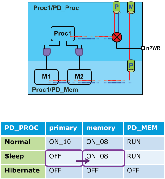
Isolation and Level Shifting
- Isolation cells are typically used to protect logic that is powered on from logic that is powered off
- Used to prevent unknown values in unpowered logic from propagating into live logic
- Can also be used to prevent leakage current from live logic from improperly powering unpowered logic
# UPF Isolation Strategies
set_isolation ISO_Proc \
    -domain PD_Proc \
    -applies_to outputs \
    -clamp_value 0 \
    -isolation_signal mISO \
    -isolation_sense low \
    -location self
use_interface_cell ISOX1 \
    -domain PD_Mem \
    -strategy ISOMem \
    -lib_cells {TechISOX1}
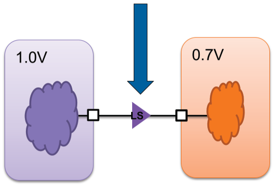
-
Level Shifting changes the voltage from one discrete value to another discrete value
-
A 1’b1 driven by 1.0V logic may be too much for 0.7V logic and likewise a 1’b1 from 0.7V logic may not translate into a 1’b1 for 1.0V logic
-
A level shifter changes a 0.7V 1’b1 to a 1.0V 1’b1 so you are propagating valid digital values through the circuit
-
State Retention
- A sequential element that can retain its value despite being powered off
- Useful to recover the last known state of the design when power was removed
- Reduces the amount of time needed reset a design to a specific state to continue operation
set_retention RET1 \
    -domain PD_Proc \
    -save_signal {SRb posedge} \
    -restore_signal {SRb negedge}
map_retention_cell RET1 \
    -domain PD_Proc \
    -lib_cells {TechRRX4}
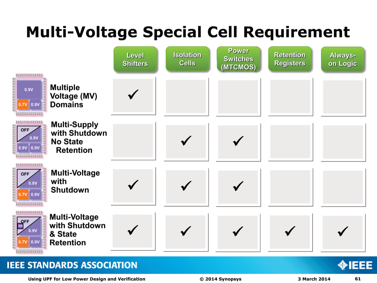
Multi-Voltage Special Cell Requirement
UPF Semantics and Usage
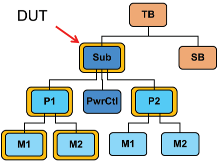
Logic Hierarchy
- Design Hierarchy
- A hierarchical description in HDL
- Logic Hierarchy
- An abstraction of the design hierarchy (instances only)
- UPF objects
- Created in instance scopes
- Referenced with hierarchical names
- Scope
- An instance in the logic hierarchy
- Design Top
- The topmost scope/instance in the logic hierarchy to which a given UPF file applies
set_design_top TB/Sub
set_scope .
set_scope P1/M1
set_scope ..
set_scope M2
set_scope /P2
Power Domains
- Partition the Logic Hierarchy
- Every instance must be in (the extent of) exactly one domain
- Can be further partitioned
- A subtree of the design can be carved out as another domain
- Unless declared
atomic- Atomic power domains cannot be further subdivided
- Can be composed into larger domains
- If all subdomains have the same primary power supply
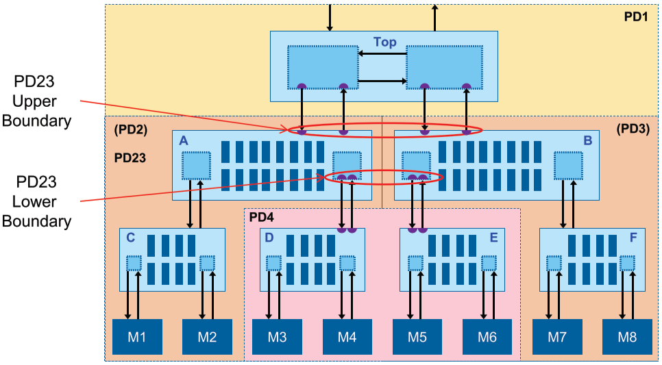
- Have an upper and a lower boundary
- Boundaries represent a change in primary supply
create_power_domain PD1 -elements {.}
create_power_domain PD2 -elements {A}
create_power_domain PD3 -elements {B}
create_power_domain PD4 -elements {A/D B/E} -atomic
create_composite_domain PD23 -subdomains {PD2 PD3}
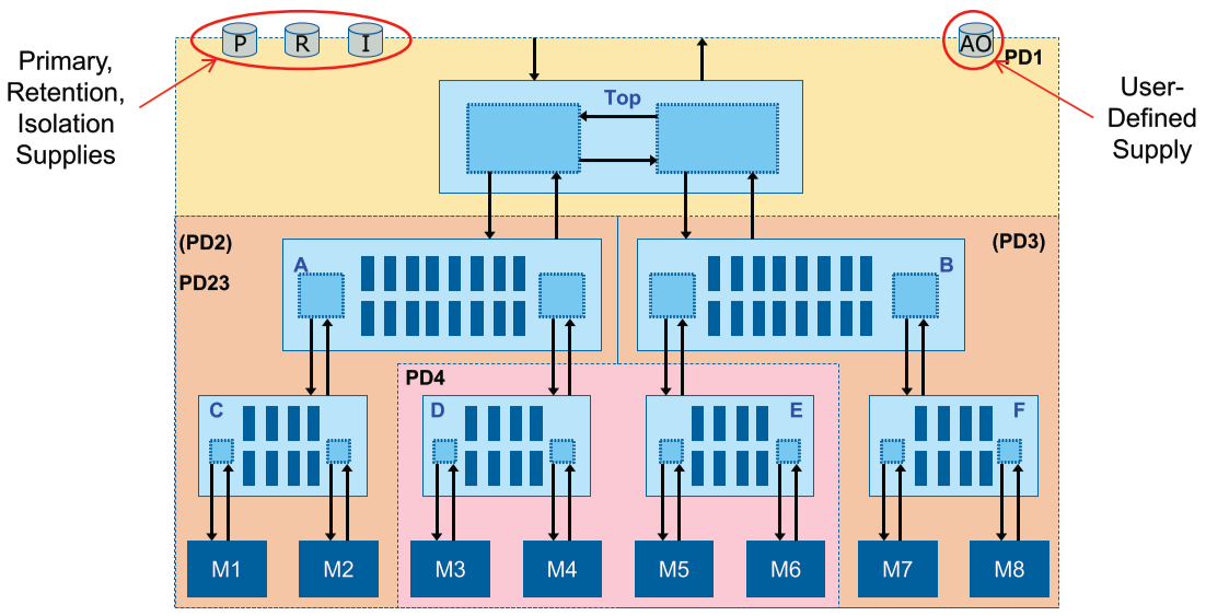
Power Domain Supplies
- Primary supply
- Provides the main power, ground supplies for cells in the domain – Can also provide additional supplies (nwell, pwell, …)
- Default retention supply
- Provides a default supply for saving the state of registers
- Default isolation supply
- Provides a default supply for input or output isolation
- Additional user-defined supplies
- Can be defined for particular needs (e.g., hard macros)
- Available supplies
- Can be used by tools to power buffers used in implementation
create_power_domain PD1 … -supply {AO}
Supply Sets
- A group of related supply nets
- Functions represent nets
- which can be defined later
- Electrically complete model
- power, ground, etc.
- Predefined supply sets
- for domains
- User-defined supply sets
- for domains (local)
- standalone (global)
- Supply set parameters
- for strategies
create_power_domain PD \
    -supply {primary} \ # (predefined)
    -supply {backup} # (user-defined)

create_supply_set Main \ # (user-defined)
    -function {power} \
    -function {ground} \
    -function {nwell}

set_isolation ISO –domain PD \
    -isolation_supply_set PD.backup
Supply Connections
Power Related Attributes
- Characteristics of a port or design element
- That relate to power intent or implementation
- Defined in UPF, HDL, or Liberty
- Liberty and HDL attributes are imported into UPF
- Used to identify power supplies for ports
- Related supplies for ports and cell pins
- Used to specify constraints for IP usage
- Clamp value constraints for isolation of ports
- Used to specify structure and behavior information
- Hierarchy leaf/macro cells, net connections, simstate use