[Emulate] Transaction Level Modeling in SystemC
- Transaction Level Modeling in SystemC
Transaction Level Modeling in SystemC1
- A high-level approach to model digital systems
- Care more on what data are transferred to and from what locations
- Care less on the actual protocol used for data transfer
- Features
- Details of communication are separated from details of computation
- Communication mechanisms are modeled as channels
- Low-level details of information exchanged are hidden in channels
- Pin level details at the structural boundary are abstracted into interface
- Transaction requests take place by calling interface functions
- Synchronization details of channels are typically abstracted into blocking and/or non-blocking I/O
- Advantages
- Enable high simulation speed by hiding uninteresting details
Timed TLM–The Very Simple Bus
Introduction of The Very Simple Bus
- Although this example is very simple and may not be practical, it provides us an essential concept about TLM in SystemC
- Some behaviors of the real bus such as arbitration, split transactions, and memory wait states are not considered
- Memory is modeled as a memory array within the bus rather than a memory module external to the bus
- Contention, arbitration, interrupts, and cycle-accuracy can be modeled with TLM without resorting to pin-accuracy
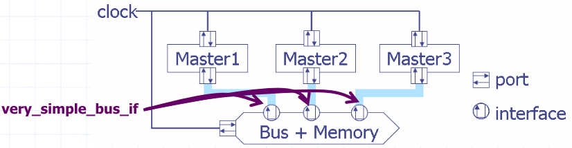
Implementation of The Very Simple Bus
class very_simple_bus_if : virture public sc_interface {
  public:
    virtual void burst_write (char *data, unsigned adder, unsigned length)=0;
    virtual void burst_read (char *data, unsigned adder, unsigned length)=0;
};
class very_simple_bus:
public very_simple_bus_if,
public sc_channel {
  public:
    very_simple_bus ( sc_name nm, unsigned mem_size, sc_time cycle_time )
    : sc_channel(nm), _cycle_time(cycle_time)
    {
    //we model bus memory access using an
    //embedded memory array
    _mem = new char [mun_size]; //set initail value of memory to zero
    memset(_mem, 0, mem_size_);
  }
  ~very_simple_bus() { delet [] _mem;}
  virture void burst_read (char *data, unsigned adder, unsigned length)
  {
    //model bus contention using mutex, but no arbitration rules
    _bus_mux.lock();
    // block the caller for length of burst transaction
    Wait (length * _cycle_time);
    // copy the data form memory of burst transaction
    memcpy(data, _mem +addr, length);
    // unlock the mutex to allow others access to the bus
    _bus_mutex.unlock();
  }
  virture void burst_write (char *data, unsigned adder, unsigned length)
  {
  _bus_mutex.lock();
  wait (length * _cycle_time);
  // copy the data form requestor to memory
  memcpy(_mem+addr, data, length);
  _bus_mutex.unlock();
  } protected: char* _mem; sc_time _cycle_time; sc_mutex _bus_mutex;
};
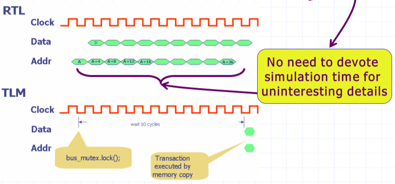
Suppression of Uninteresting Details
- Burst transfer may take many cycles to complete
- The bus is merely doing routine works
- Clients that have pending bus requests are just waiting
Timed TLM – The Simple Bus Design
Introduction of the Simple Bus Design
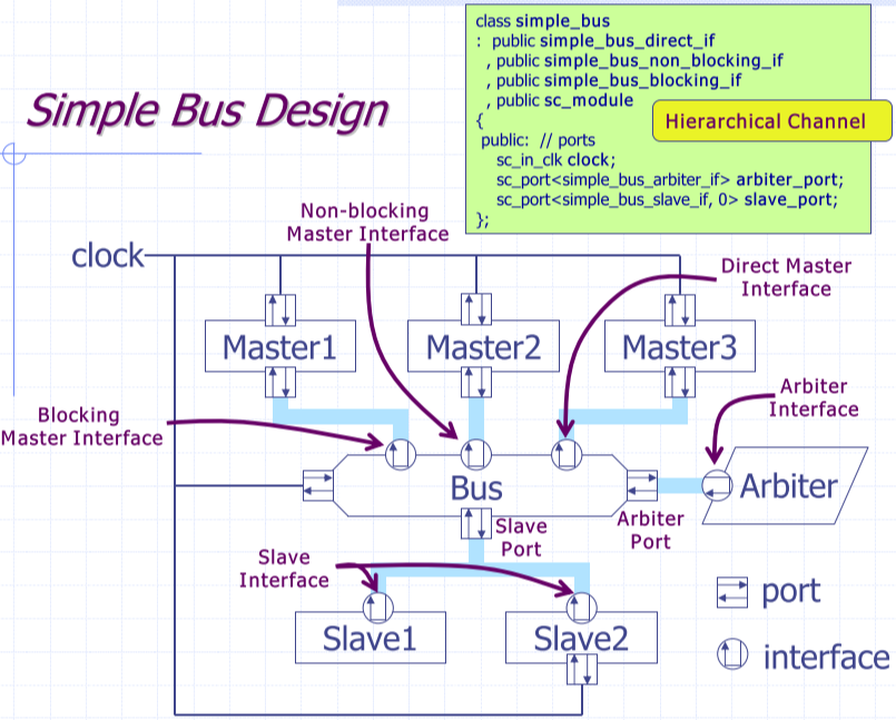
Structure of the Simple Bus Design
- Masters (CPUs, DSPs, Arithmetic Intensive ASIC)
- Initiate transactions on the bus
- Bus
- Allow the masters and slaves to communicate using bus transactions
- Slaves (ROMs, RAMs, I/O Devices, Hardware Accelerators)
- Response to the bus requests
- Arbiter
- Arbitrate which master can issue the transaction via the bus
- Select a request to execute from the competing bus requests
- When a master is granted access to the bus, the requests from the other masters are queued by the bus and executed in later cycles
- Clock generator
- Provide the system clock that can synchronize the blocks
- Master 1: Blocking Master
- Use blocking master interface
- Model high-level software that initiates transactions as they execute
- Master 2: Non-Blocking Master
- Use non-blocking master interface
- Model detailed processor (instruction-set simulator, ISS) that must execute on every clock edge even when waiting for its bus transactions to complete
- Model Master 3: Direct Master
- Use direct master interface
- Print debug information about the contents of the memories
- Does not represent a block that will exist in the real world
- Slave 1 (Fast Memory)
- Implement slave interface
- Model a random access memory that supports single-cycle read/write operation with no wait states and no clock port
- React immediately to the bus request and set the status
- Slave 2 (Slow Memory)
- Implement slave interface
- Model a random access memory which takes a few number of cycles to complete a read/write operation, and contains a clock port
- Wait states
- Additional cycles that a slave takes to complete an operation
- All other activity on the bus waits until the operation completes
Features of the Simple Bus Design
- High performance, cycle-accurate, platform transaction-level model
- Cycle-accurate transaction level modeling
- Model is done at transaction level
- Model is based on cycle-based synchronization
- Cycle-based synchronization
- Model the data movement on a clock by clock basis
- Sub-cycle events are of no interest
- Transaction-based modeling
- Communication between components are described as function calls
- Sequences of events on a group of wires are denoted by a set of function calls in an abstract interface
- Two-phase synchronization
- Modules attached to the bus execute on the rising clock edge
- The bus executes on a falling clock edge
- Easy to add different kinds and numbers of masters or slaves
- Masters connect to the bus using just one port connection
- Slaves connect to the bus using SystemC multi-port feature
- Easy to change the arbitration policy by replacing the arbiter
- Arbiter is a separate module from the bus
Ideas behind the Simple Bus Model
- Modeling efforts
- Relatively easy to develop, understand, use, and extend
- Capable of being constructed very early in the system design
- Enable designers to explore implementation alternatives
- Make design trade-offs before it is too late or too expensive to do so
- Accuracy
- Being fully cycle-accurate
- Being able to accurately simulate with both the SW and HW components
- Fast and accurate enough to validate SW before more detailed HW models or implementations are available
- Speed
- Capable of simulate at the speed of more than 0.1MHz
- Fast enough to allow meaningful amounts of SW to be executed along with HW models
Master Interface
Introduction of Master Interface
- Describe the communication between the master and the bus
- Master interface is used by masters and implemented in the bus
- 3 sets of master interface functions
- Blocking master interface
- Non-blocking master interface
- Direct master interface
- Multiple masters can be connected to a bus
- Each master is independent of the others
- Each master can issue a bus request at any time
- Each master is identified by a priority number
- The lower the priority is, the more important the master is
- Each master interface function use this priority to set the importance of the call
- A master can reserve the bus for a subsequent access
- The bus can be locked for the same master in consecutive cycles
Blocking Master Interface
- These methods return only after the transaction is completed
- Used by high-level software that generate read/write transactions
- Such software model is not cross-compiled to a target processor and executes directly on the host workstation
class simple_bus_blocking_if : public virtual sc_interface
{
public: // blocking BUS interface
virtual simple_bus_status burst_read(unsigned int unique_priority
  , int *data
  , unsigned int start_address
  , unsigned int length = 1
  , bool lock = false) = 0;

virtual simple_bus_status burst_write(unsigned int unique_priority
  , int *data
  , unsigned int start_address
  , unsigned int length = 1
  , bool lock = false) = 0;
}; // end class simple_bus_blocking_if
unique_priority: (1)The id of the master (2)The importance of the masterbool lock: If lock is set, (1) The bus is reserved for exclusive use for a next request of the same master (2) The function cannot be interrupted by a request with a higher priority
Return Values of Master Interface Methods
SIMPLE_BUS_REQUEST- The request is issued and placed in the queue
- The status in all cases right after issuing the request
- The status only changes when the bus processes the request
SIMPLE_BUS_WAIT- The request is being served but not completed yet
SIMPLE_BUS_OK- The request is completed without errors
SIMPLE_BUS_ERROR- The request is finished but the transfer is not complete successfully
Non-Blocking Master Interface
- These functions return immediately, but the read/write will take more than one cycle when competing requests exist
- Caller must check the status of the last request using
get_status() - Used by ISS models which cannot be suspended while they have outstanding bus requests
class simple_bus_non_blocking_if : public virtual sc_interface{
public:
  // non-blocking BUS interface
  virtual void read (unsigned int unique_priority
    , int *data
    , unsigned int address
    , bool lock = false) = 0;
  virtual void write (unsigned int unique_priority
    , int *data
    , unsigned int address
    , bool lock = false) = 0;
  virtual simple_bus_status get_status (unsigned int unique_priority) = 0;
}; // end class simple_bus_non_blocking_if
- A non-blocking request can be made if the status of the last request is either
SIMPLE_BUS_OKorSIMPLE_BUS_ERROR - An error message is produced and the execution is aborted when a new request is issued and the current one is not completed yet
Direct Master Interface
- These functions provide instantaneous read/write
- Simulated time will not advance and scheduler will not intervene
- Data accesses go through the bus for proper routing of the requests
- Data transfer is done without using bus protocol
- Used for creating simulation monitors
- Enable debuggers running on top of ISS models to read/write to slaves without waiting for the simulation time to advance
class simple_bus_direct_if : public virtual sc_interface {
public:
  // direct BUS/Slave interface
  virtual bool direct_read(int *data, unsigned int address) = 0;
  virtual bool direct_write(int *data, unsigned int address) = 0;
}; // end class simple_bus_direct_if
Slave and Arbiter Interfaces
Slave Interface
- Describe the communication between the bus and the slave
- Slave interface is used by the bus and implemented by every slave
- By definition, the slaves thus play the role of channels
- 2 sets of slave interface functions
- Normal slave interface: Serve the default read/write to and from the slaves
- Direct slave interface: Similar to direct master interface
- Multiple slaves can be connected to a bus
- Two functions can be used to obtain the memory range of a slave
- unsigned
int start_address()const; - unsigned
int end_address()const;
Normal Slave Interface
- The read/write function performs a single data transfer and returns immediately, and caller must check the return values
- Return values of slave interface methods
SIMPLE_BUS_WAIT: the slave issues a wait stateSIMPLE_BUS_OK: the transfer was successfulSIMPLE_BUS_ERROR: an error occurs during the transfer
- If the return status is
SIMPLE_BUS_WAIT, caller must call the function again until the status becomesSIMPLE_BUS_OK
class simple_bus_slave_if : public simple_bus_direct_if {
  // also sc_interface
public:
  // Slave interface
  virtual simple_bus_status read(int *data, unsigned int address) = 0;
  virtual simple_bus_status write(int *data, unsigned int address) = 0;
  virtual unsigned int start_address() const = 0;
  virtual unsigned int end_address() const = 0;
}; // end class simple_bus_slave_if
Arbiter Interface
- Describe the communication between the bus and the arbiter
- Arbiter interface is used by the bus and implemented in the arbiter
- By definition, the arbiter thus plays the role of channel
- Arbitrate competing requests issued by different masters
- The bus passes its outstanding requests to an arbiter on each cycle
- One of the requests is selected for execution based on arbitration policy while the others are kept in the
SIMPLE_BUS_REQUESTstate
class simple_bus_arbiter_if : public virtual sc_interface{
  public:
    virtual simple_bus_request* arbitrate(const simple_bus_request_vec &requests) = 0;
}; // end class simple_bus_arbiter_if
Master and Slave Request Status
- Master request status (read by the master)
SIMPLE_BUS_REQUEST: The request is issued and placed in the queueSIMPLE_BUS_WAIT: The request is being served but not completed yetSIMPLE_BUS_OK: The request is completed without errorsSIMPLE_BUS_ERROR: The request is finished but the transfer is not complete successfully- Slave request status (read by the bus)
SIMPLE_BUS_WAIT: The slave issues a wait stateSIMPLE_BUS_OK: The transfer was successfulSIMPLE_BUS_ERROR: An error occurs during the transfer
Concepts of Operations
Overall Execution Scheme
- On the rising edge of the clock
- Masters execute and may send requests to the bus
- Bus maintains a set of outstanding requests including unfinished ones from past cycles
- On the falling edge of the clock
- Bus calls arbiter to select a request for execution
- Bus looks up the address of the request to determine the target slave
- Bus invokes the
read()/write()functions of the target slave - Functions return and indicate if the slave issues wait states
- Bus will reissue the request on the next cycle upon receiving wait states
- Bus updates the status of the original master once the slave completes the request
Two-Phase Synchronization
- Masters and slaves are active on the rising edge of the clock
- Bus and arbiters are active on the falling edge of the clock
- Two-phase synchronization
- Communication between modules attached to the bus go through the bus
- Communication is delayed by a clock cycle
- On the rising edge of the clock, no state changes of the bus are visible
- On the falling edge of the clock, the bus arbitrates the competing requests
- Request-update mechanism
- Communications between processes go through the primitive channels
- Communication is delayed by a delta-cycle
- In the evaluation phase, no state changes of primitive channels are visible
- In the update phase, primitive channels resolve competing requests
- Triggering the bus using the clock falling edge is just a technique
- Actual implementation may not use the falling edge of the clock
- Designs with the two-phase synchronization and deterministic arbitration rules are deterministic
- The order of process execution will not affect the execution results
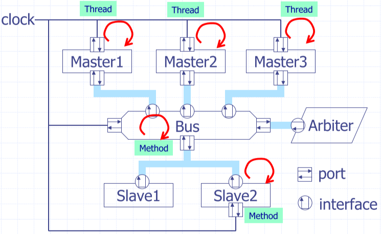
High-Performance Modeling Techniques
Introductions
- Simple modules are modeled without any processes at all
- Example: fast_mem and arbiter
- Blocks to be activated most frequently should use
SC_METHOD SC_METHODconsumes less memory and execute more quickly- Frequently activated processes should do as little work as possible
- Example: in slow_mem, there is a clocked
SC_METHODthat simply decrements a counter to indicate when the wait states comes to completion
Comparisons between TLM and RTL
- RTL uses signals for communication; TLM employs transactions
- Transactions are modeled by function calls
- Both control and data are transferred along with function calls
- There is no pin-accuracy
- Data can be bundled and passed more efficiently
- Pointers to data are transferred between modules by transaction
- Enable one module to very efficiently copy blocks of data to another
- Example: the
burst_read/burst_writetransactions
- RTL uses low-level bit vectors; TLM uses high level C data-types
- RTL uses static sensitivity; TLM uses dynamic sensitivity
- RTL modules execute on every cycle even if no work is being done
- TLM modules enable execution when they have real work to perform
- Processes are suspended until the bus requests complete
Common Questions
- What is the distinction between modules and hierarchical channels?
- In an informal way
- Hierarchical channels: implement interface functions and contain no ports
- Modules: do not implement interface functions and contain ports
- In reality: Hierarchical channels and modules are the same thing
- In simple_bus design
- Blocks implementing transactions are designed to be channels that inherit form their transaction interface
- Blocks that initiate transactions are designed to be modules that allow them to access the channels
- The bus implements several interface functions and it also has ports to access the interface of the slaves and arbiter
- Why do slaves implement slave interface rather than having normal ports like other modules?
- Eliminate the need for a process within the fast_mem and arbiter
- Allow minimizing the amount of works in the process of slow_mem
- Why are multiple slave channels attached to the same port on the bus?
- Do not want to fix the number of slaves
- Allow binding as many slaves to the bus as wished during elaboration
- Multi-port feature of SystemC
sc_port<simple_bus_slave_if, 0> slave_portslave_port.size()returns the number of channels bounded to the portslave_port[N]separates slave channels bounded to the port
-
IOC5080(5940) System Model Design and Verification, Department of Computer Science, National Chiao-Tung University ↩